This offer is currently only addressed to commercial customers. All prices are exclusive of goods and services tax (GST).
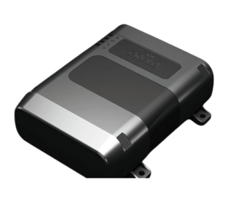
Bharat 101Plus 4G with CAN
_9.svg)

PRODUCT OVERVIEW
'1. Identification of Installation location
- The device contains the radio module which will transmit and receive the GSM and GNSS signals
- The device will not operate in extreme heat conditions. Operating condition of the device need to checked
- The device requires covert installation where the devices should not be made easily accessible so that the thieves can find the devices and remove them
- The metal over and around the device will affect the GNSS signals which will be received from the device
- The device should have maximum visibility to the sky avoiding metal parts
- The device should not be installed near the moving parts as it may affect the device performance and might damage the device
- There should not be any ECUs 20 cms around the location chosen
- The windshield heaters affect the reception of the GNSS signals
2. Recommended Install Locations
- Inside/Decide/Above the glove box
- Behind the dashboard, Top of the dashboard, if the dashboard is made up of metal
- Test all the functioning of the vehicle systems before you start the installation of the device. If you find any defects immediately inform the customer about the fault of the vehicle
- After connecting the wires, isolate the connection with insulation tape and on top of the insulation fasten with cable ties
- Wires should be connected while module is not plugged in
- Wires should be fastened to the other wires or non-moving parts. Try to avoid heat emitting and moving objects near the wires
- The connections should not be seen very clearly. If factory isolation was removed while connecting wires, it should be applied again
- If the wires are placed in the exterior or in places where they can be damaged or exposed to heat, humidity, dirt, etc., additional isolation should be applied
- Wires cannot be connected to the board computers or control units
- Use only a multi-meter to identify the different wires in the vehicle system. Don’t use the test lamp as it will consume more current, may damage the equipment in the vehicle
- To connect the -Ve terminal of the device, connect a lug properly crimped to the negative wire of the device and screw it to chassis using crews or a bolt. Ensure that connection is good and stable
- After all the wires are connected use the cable ties to secure all the wires and cables to fixed elements in the vehicle such as metal parts, but not to the parts that are removed during vehicle service
- Attach the device to a fixed support by using double-sided tapes and cable ties. Make sure that the device will not get loose
- When the installation is complete, clean the vehicle and fasten all the screws with originals and lock the clip mounts properly
- Test the functioning of the vehicle systems before winding up the installation
- Test the communication with the server with proper GNSS fix status before leaving the vehicle
3. Location to Avoid
- Close to Airbags
- Under the Roof of the Vehicle
- Inside AC Duct, Engine Compartment, Boot
- Near the Fuel Tank
- Near the Speakers and Near Antenna or the Radio Transmitters
- Outside the Passenger Compartment of the Vehicle
4. Device orientation
- The device has an internal GNSS antenna and the accuracy of the location which is received is purely dependent on the quality of the signal received. So the orientation of the device has a greater impact on the GNSS signal reception. It is mandatory to keep the LED side of the device facing the sky, unobstructed by any metal. In any case, there should be no metal on top of the device for up to 30-40 cm around the device. It is not recommended to tilt more than 50 degrees to the horizontal axis to avoid the poor reception of the GNSS signals. The orientation of the device with respect to the driving axis plays a major role in the case if the eco-driving source is selected as Accelerometer. Even though there is an option to configure the eco-driving axis, the device should be mounted parallel to the vehicle’s horizontal axis.